Teensy telemetry on Taranis
To have flight telemetry on Taranis X9D Plus, one has to pick up telemetry coming from both Pixhawk (2.1 in my case) and other sensors (FLVSS in my case) and send it to the receiver (X8R in my case). After all, Taranis X9D Plus is a full-fledged «Digital Telemetry Radio System», what can possibly go wrong? :)
The problem
Ok, the first problem is that Taranis is made by FrSky and so it wants telemetry in FrSky format over SBUS (not Smart Port, they are different, mind you!), a format that FLVSS and other sensors already support and provide, so almost zero work on that side. Also, SBUS looks like a nice protocol: up to 16 sensors that can be chained, only three wires and more. At first, I thought this job was perfect for the Raspberry Pi1, also because I wanted (and I still want) to have every bit of information available on the Raspberry. So the genius idea was to capture both Pixhawk telemetry and SBUS protocol on the Raspberry and exit to the X8R receiver with SBUS. However, after having read a few lines about SBUS protocol and, specifically, these words:
«SBUS is an interesting thing. It uses a 100000 baud inverted UART with a 25 byte transmission»
and having realized that:
- it’s not so easy to sample stuff at 100k baud on a Raspberry PI;
- there is a library for bringing SBUS on RPI, but it looks “a little bit untested”;
- in case of problems, this is how SBUS data looks like (yes it’s disturbing like a CANOpen frame):
using real term i get the data fine, consistent etc... 0F E0 03 5F 2B C0 C7 0A 56 80 0F 7C 00 00 00 00 00 00 00 00 00 00 00 0C 00 0F E0 03 5F 2B C0 C7 0A 56 80 0F 7C 00 00 00 00 00 00 00 00 00 00 00 0C 00 0F E0 03 5F 2B C0 C7 0A 56 80 0F 7C 00 00 00 00 00 00 00 00 00 00 00 0C 00 but using the serial library mentioned here, and others, the best i can get is 0C 00 0F E0 03 5F 0F 7C 00 00 00 00 00 0F E0 C7 0A 56 00 00 00 00 0F E0 03 5F 2B 7C 00 00 00 00 00 00 0F E0 0A 56 80 00 00 00 00 0F E0 5F 2B C0 C7 00 00 00 00 0C 00 0F E0 03 80 0F 7C 00 00 00 00 0F E0 C0 C7 0A 00 00 00 0C 00 0F E0 03 5F 0F 7C 00 its as if bytes being dropped, //also tried 99 and 100k. port0.begin(98000,SP_2_STOP_BIT | SP_EVEN_PARITY | SP_8_BIT_CHAR); - whenever you read that a protocol is «interesting» it means that you’ve already taken the reverse engineering route and I didn’t want to reverse engineering anything this time. When they work, protocols are transparent and people almost never even realize that they are there. This time (like most other times) I wanted to completely ignore the details of underlying stuff. I just wanted telemetry on the radio.
Anyway, having the telemetry on the Raspberry Pi is still an important feature and I’ll try again to acquire it in the future. It should not be difficult to mirror a telemetry port and read its RX serial on the RPI, there is also a nice diagram here:
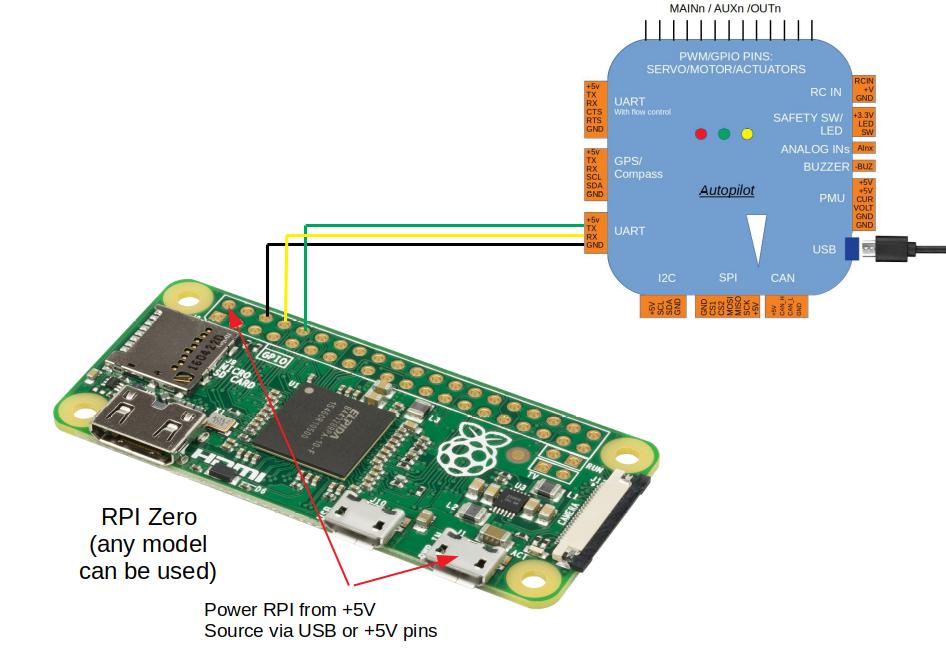
It would be much harder to hook the RPI to the SBUS chain like it was another sensor, and I don’t know if it’s worth the hassle.
What went right
Ok, back to our scenario: Pixhawks’ telemetry is in MAVLink format over simple RX/TX serial2 so we’ll need something able to chew it both at the software and signal level and spit it out in the correct HW/SW formats.
This thing exists and is a Teensy 3.2!

Nonono, not the big one, that one is a Raspberry Pi 3, the other one, the tiny, teeny, Teensy, actually! :)
To flash the Teensy (3.2 in my case) is quite an easy task. It’s just a matter of pointing to the Teensy Telemetry Project page and download all the bit and pieces you’ll need for the operation. First, you’ll need the program to flash the Teensy: it’s called «loader» and you can find it here. At the top of this page, you can see the loader for Windows (but you don’t use Windows, right? Naaa, why you should…) and a zip file with a couple of .hex firmware files ready to be flashed to the Teensy to make it blink fast and then slow again as it came out of the factory.
In the menu on the left, you can choose your OS (Ubuntu in my case) and the flash util, GUI or CLI3. I downloaded and istalled the udev rule with a simple:
sudo cp 49-teensy.rules /etc/udev/rules.d
Then I cloned the github repo, built with make (it’s just one C file) and run it. Here is the video of the flashing procedure, it’s really simple.
Finally, a little bit of soldering and this is the result. Quite easy actually.

Now what should have been the easy part. :)
What went wrong
On paper, that was the hard part and it went really smooth. I then went on, connected everything to the drone and tried to discover the sensors on the Taranis.


Nothing.
Ok, when things like this happens, one have to step back and redo almost everything until the problem(s) are found. Also, trying to read more carefully the assembly instructions may help. And so I did. I re-checked everything from soldering to test the continuity through software. And I thought I found my problem there. Reading more in detail the last pages of ScottsFly telemetry post I began to realize that my version of OpenTX 2.24 was not compatible with ScottsFly telemetry code.
Even if I read a couple of times that other people managed to make it work on OpenTX 2.2, I decided that I wasn’t able to detect sensors from Taranis because of that, and the next logical step was to downgrade it to OpenTX 2.1.9. Fortunately, the procedure is quite easy (except that you loose all your settings, models, sounds, etc.). Fortunately, I didn’t customize my Taranis yet, so I made this step with ease.
The procedure completed correctly, I tried again to discover sensors: nothing. At that point, I figured out my other big weak point: I never clearly understood the binding procedure: I did it at the very beginning of my drone experience (watching this beautiful video) but since then I’ve fiddled with settings of the Taranis way too much, even on the binding part. Maybe I just bound the Taranis in the wrong way since the beginning or I broke something in the following experimentations, who knows.
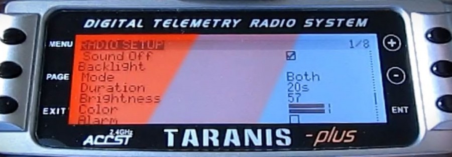
So, reading this page, I tried to understand for real what the binding process was. I’m still not understanding it fully, what I realized is that on the first time I bound to the receiver in Mode 5 (D16) and that was the mode I actually wanted the Taranis bound now. However, I also noticed that in my current settings, all the 16 channels were used for commands, with Channel Range [CH1-16]. So maybe this was the reason why the telemetry wasn’t sent back.
So I re-bound it, but this time I left the channel range setting on its default: Channel Range [CH1-8], like this:
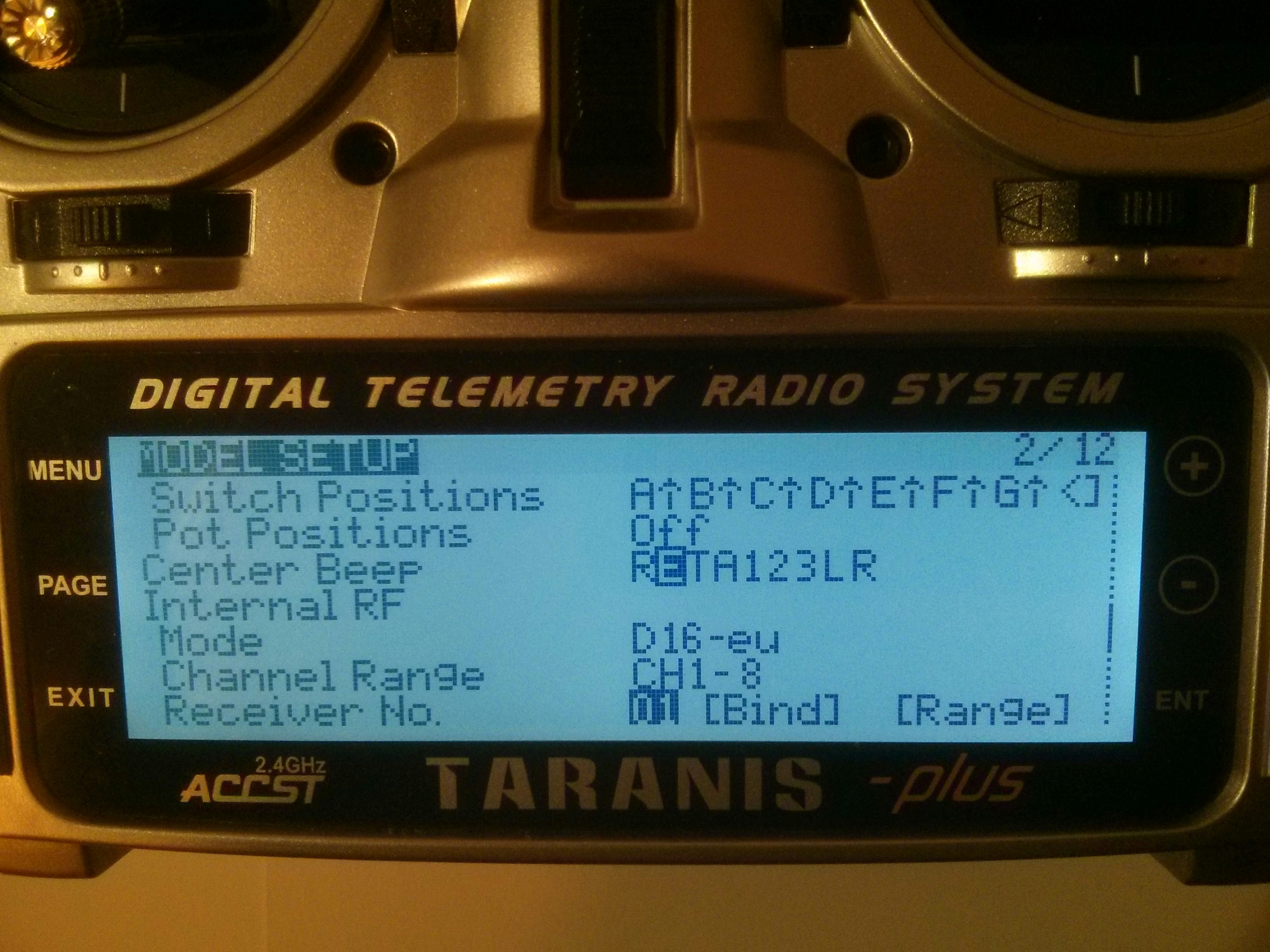
And it worked! Sensors were discovered correctly – even sensors with obscure meaning or doubtful usefulness – but they were discovered!
Finally, here is a pic of my Teensy 3.2 soldered and mounted onboard.


And now… just for you… a pseudorandom list of links of questionable value!
- Norway regulations – just in case you plan to fly in Norway;
- OpenSky, another alternative to ScottsFly Telemetry;
- A guy that built his Teensy better than I did;
- MavLink_FrSkySPort – a software only (no Teensy) version of ScottsFly Telemetry (originally forked from Clooney82 project);
- Ardupilot official page about Pixhawk telemetry;
- FlightDeck, Craft & Theory’s beautiful Taranis App – spoiler: you have to pay for it.
- Pixhawk 2.1 pinout – if you want to carve telemetry out of it for your own purposes;
- My excellent job doing exactly that;
- Another view of Pixhawk 2.1 telemetry pinout – because on original Pixhawk, RX and TX are reversed!
- How to chain more than one FLVSS sensors;
-
Still to be installed on the drone. ↩
-
with a decent 5V power supply as well, so you may also hook other sensors to it. ↩
-
command-line only for me, thanks. ↩
-
I updated the X8R firmware the day before!!! ↩